Robert Weldon’s ‘Hydrostatick’ or Caisson Lock
When canal building was at its peak, many suggestions were put forward for alternatives to conventional locks. The chief disadvantages of conventional locks were:
- Profligate use of water, a whole lock full being needed for each boat passing through.
- Limited rise or fall unless very large quantities of water were available for a deep lock (such as alongside a river)
- The time taken to negotiate a flight of locks where large changes in canal level were accommodated.
In 1794, the Committee of the S.C.C. was made aware of a new design of boat lift, Robert Weldon’s Caisson Lock, a model of which was undergoing trials on the Shropshire Canal at Oakengates. This appeared to overcome all the main disadvantages of conventional locks and only three of these machines would be needed to take the place of the flight of 22 locks planned at Rowley Bottom near Combe Hay. By 1796, construction on the first Caisson was started.
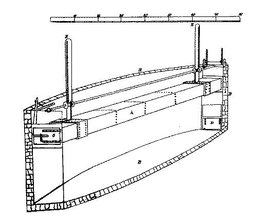
The drawing of the Caisson Lock which appeared in Robert Weldon’s patent
Construction of the first Caisson Lock (the uppermost of the flight) was completed and some work was begun on the site for the second one. During preliminary trials, several difficulties were found in the operation of the mechanism, which was inherently unstable due to the quantity of water inside the ‘submarine’ box. Unless the box was maintained absolutely level by a parallel-motion mechanism (a pair of racks and pinions appears to have been proposed), the water would run to the lower end, making it heavier and forcing it lower still. On one occasion, this resulted in the breakage of the parallel-motion mechanism and one end of the box plunged to the bottom of the chamber.
To keep the box transversely stable, a system of rollers running against the sides of the chamber (probably bearing on iron plates) was used. This system eventually became distorted, probably by geological movements of the hillside and swelling of the surrounding soil when water leaking through the chamber masonry saturated it. The seriousness of the distortion was revealed when the S.C.C. Committee decided to risk a ride in the lift – which then become stuck in a submerged position. To free it, the water in the chamber was drained-off and the Committee members were eventually rescued on the point of suffocation.
At this point, the Committee lost all confidence in the Caisson Lock system and decided to revert to the original plan of a flight of 22 conventional locks.
The intended operating procedure for the Caisson Lock is not known, but it can be deduced from available knowledge. There was no obvious requirement for the boatman to ride inside the caisson with his boat – in fact there were several good reasons why he should not do so:
- It was extremely dangerous if anything went wrong
- He was needed to take the horse to the lower level while the caisson operator lowered the boat
- It was easier to load and unload the boat from a position outside the caisson
This gives us a fairly good idea how the caisson might have looked if it had ever come into general use:
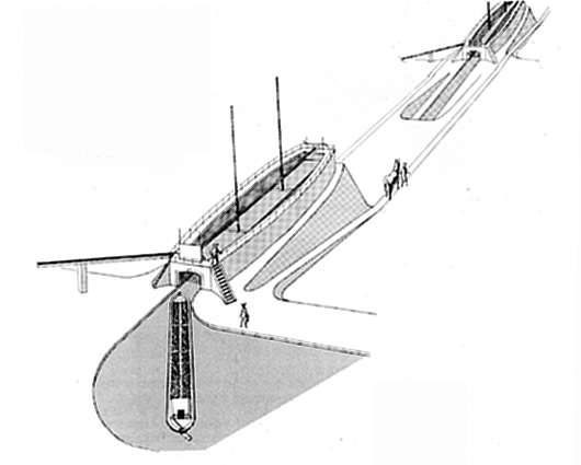
Drawing copyright Mike Chapman
WHERE WERE THE CAISSONS?
Only one caisson was ever completed and that was demolished at about the time the lock flight was built. The masonry must have been massive, so it would hardly be surprising if the huge blocks of stone from the caisson walls were reclaimed in some way and re-used during the building of the lock flight or other structures on the canal. (The coping stones on locks 1 to 19 are very large and the quantity would be just sufficient to account for all the stone which could be recovered from the caisson chamber – but this is only speculation.)
Recently a map has come to light, which has put paid to most of the speculation about where the caissons were intended to be built. The Smith-Carey map in Taunton County Archives clearly shows the line of the canal and the inclined plane which replaced the caisson; but also shows another line which appears to have been drawn on the map and then erased. This line joins the upper and lower parts of the canal and crosses the contours of a steep slope at two places where the caissons might have been expected.
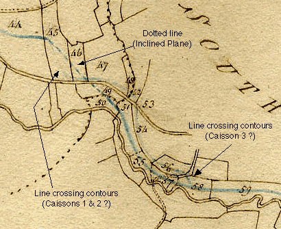
Part of the Smith-Carey Map showing the upper canal (44), the lower canal (59) and two possible routes for joining them. The dotted line is believed to be the route of the inclined plane, but the fainter line, which crosses contours at the points indicated, could mark the position of the caissons.
Photograph copyright Daniel Brown
From this evidence, it seems most likely that the first and second caissons were to have been built in the field marked 45, which is still identifiable today as Caisson Field, part of the grounds of Caisson House. The third caisson, on which work was probably never begun, would have been built between the parish road and the present-day position of Lock 20 (In field 58).